The Smooth tool is used to control the number of facets defining a surface and the number of points defining a curve.
A denser mesh generated by Bezier interpolation replaces the original facets.
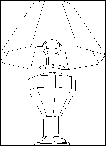
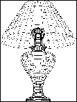
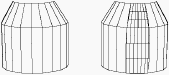
Example of use of the Smooth tool |
|
You can choose from:
· Five smoothing methods for polygonal surfaces
· Three smoothing methods for polygonal curves
· Smoothing on two axes for NURBS objects
![]()
It is not possible to smooth a group of objects that are not of the same type. (That is, it is not possible to smooth a group of objects including NURBS and polygonal objects).
![]()
This tool adds an additional finishing level which will be editable by the tools using the Dynamic Geometry. For more information, see the chapter User Manual/ The Objects/ Dynamic Geometry.
![]()
The Smooth tool can be very useful for subdividing a segment into N sub-segments of equal size. You simply create a single segment (with only two points: a starting point and an ending point) with the Polyline tool, then use the Smooth tool to subdivide it.
q Smoothing polygonal surfaces
From the five available methods, select the one you want. At any time, you can switch from one smoothing method to another by simultaneously pressing the “Ctrl” key and the spacebar.

|
|
|
|
|
|
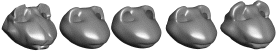
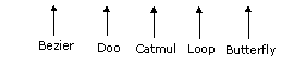
Un-smoothed object |
Bezier smoothed |
Doo smoothed |
Catmull smoothed |
Loop
|
Butterfly smoothed |
![]()
Bezier smoothing provides a sub-palette to manage areas to be excluded from the smoothing operation (breaks).
![]()
If you change the view, the smoothed appearance will not remain displayed. However, Amapi 3D will retain the smoothing information for the element.
Usage:
1. Selection of the element or a part of the element to be smoothed.
· Click with the Wand on the element to be smoothed. It becomes the current element.
· To restrict the action to a part of the element: use the Lasso or the Bullseye in the Assistant Palette or by using the shortcut (PC: Click on the right mouse button, Mac: Option-click).
2. Select the Smooth tool.
· Click on the icon depicting the tool in the palette. Amapi 3D displays a palette for this tool.
![]()
3. Select the Smoothing method.
· If you enter the tool for the first time, the default method is Bezier smoothing.
· If you have already used smoothing on the current object, Amapi 3D selects the last method used.
· If the current mode (outlined in yellow) is not the one you want, click on the icon that corresponds to the desired mode.
You can switch from one smoothing method to another by simultaneously pressing the “Ctrl” key and the spacebar.
Amapi 3D displays the sub-palette for the Bezier smoothing method and a preview of the smoothed object (in red).
4. Range and/or smoothing angle modification.
The SMOOTHING RANGE: defines the number of faces (for a surface) or edges (for a curve). The greater the range value, the finer the smoothing.
The BREAK ANGLE: If the angle between two adjacent faces is less than the break angle, the two faces will not be smoothed.

The data palette displays the range and the angle. There are two ways to set these values:
· You can switch from one data field to another by pressing the spacebar. The editable data will appear darker. Use the tuner (“+” or “-” keys, or click on the “+” or “-” icons of the Assistant Palette) to set the desired value.
· If you prefer, press the Tab key until you reach the field you want to edit, set a value, and validate.
5. Preview.
Amapi 3D displays a preview of the smoothing.
For surfaces, a fine red grid appears automatically on the object.
![]()
Effect of smoothing on a curve.
Effect of smoothing on a surface.
6. Tuning:
For Bezier smoothing, the following sub-palette is displayed:
![]() Break per point:
Break per point:
Break per POINT creates a break at the end of each edge adjacent to this point and causes a “flatness” of the surface on this point.
The selection is made with the Lasso or the Bullseye in the Assistant Palette or by using the shortcut (PC: Click on the right mouse button, Mac: Option-click).
![]() Break per edge:
Break per edge:
Break per EDGE forces the generated surface to be “stuck” to the broken edge.
The selection is made with the Lasso or the Bullseye in the Assistant Palette or by using the shortcut (PC: Click on the right mouse button, Mac: Option-Click).
![]() Partial smoothing:
Partial smoothing:
This tool allows you to smooth only a part of an object.
The selection is made with the Lasso or the “Face selector” in the Assistant Palette or by using the shortcut (PC: Click on the right mouse button, Mac: Option-Click).
![]() Delete all breaks
Delete all breaks
7. Display the integrality of the smoothing on the whole selected surface (optional).
· If you don’t want to use this step, your object will be smoothed, but on-screen you will only see its smoothing curves (figure 2). When you will export the object or do a rendering, the faces will be generated (figure 3).
· If you want to see your smoothed object in its entirety (figure 3), press the Return key. Caution: this kind of display increases the display time.
|
|
|
Figure 1
|
Figure 2
|
Figure 3
|
![]()
This manipulation increases the display time. The more an object is smoothed, the slower the display.
![]()
If you don’t do this step, the smoothed aspect of your object will only be symbolized by the display of the smoothing curves instead of its initial edges.
When you export it or do a rendering, the faces will be generated.
![]()
Try a simple rendering on a symbolized smoothing display model to check if it is smoothed.
8. Ending the tool action.
Put the tool aside to end the action (depending on the interface). See chapter User Manual/Tools/Generic use of a tool/How do you end a tool action?
|
Practical exercises:
|
![]()
This is an “Internal” smoothing, which means that it uses the surface or volume to be smoothed as a control shape.
Usage:
1. Selection of the element to be smoothed.
· Click with the Wand on the element to be smoothed. It becomes the current element.
2. Select the Smooth tool.
Click on the icon depicting the tool in the palette. Amapi 3D displays a palette for this tool.
![]()
3. Select the Smoothing method.
· If you enter the tool for the first time, the default method is Bezier smoothing.
· If you have already used smoothing on the current object, Amapi 3D selects the last method used.
· If the current mode (outlined in yellow) is not the one you want, click on the icon that corresponds to the desired mode.
You can switch from one smoothing method to another by simultaneously pressing the “Ctrl” key and the spacebar.
4. Range of smoothing modification.
The SMOOTHING RANGE: defines the number of faces (for a surface) or edges (for a curve). The greater the range value, the finer the smoothing.
The data palette displays the range. There are two ways to set these values:
· Use the tuner (“+” or “-” keys, or click on the “+” or “-” icons of the Assistant Palette) to set the desired value.
· If you prefer, press the Tab key until you reach the data you want to edit, set a value and validate.
5. Smoothing.
Amapi 3D displays the smoothed object in its entirety.
If you are satisfied with the result, go to the next step.
If not, you can change the smoothing range or select another smoothing method.
6. Ending the tool action.
Put the tool aside to end the action (depending on the interface). See chapter User Manual/Tools/Generic use of a tool/How do you end a tool action?
![]()
This is an “Internal” smoothing, that means it uses the surface or volume to be smoothed as a control shape.
Usage:
1. Selection of the element to be smoothed.
· Click with the Wand on the element to be smoothed. It becomes the current element.
2. Select the Smooth tool.
Click on the icon depicting the tool in the palette. Amapi 3D displays a palette for this tool.
![]()
3. Select the Smoothing method.
· If you enter the tool for the first time, the default method is Bezier smoothing.
· If you have already used smoothing on the current object, Amapi 3D selects the last method used.
· If the current mode (outlined in yellow) is not the one you want, click on the icon that corresponds to the desired mode.
You can switch from one smoothing method to another by simultaneously pressing the “Ctrl” key and the spacebar.
4. Range of smoothing modification.
The SMOOTHING RANGE: defines the number of faces (for a surface) or edges (for a curve). The greater the range value, the finer the smoothing.
The data palette displays the range. There are two ways to set these values:
· Use the tuner (“+” or “-” keys, or click on the “+” or “-” icons of the Assistant Palette) to set the desired value.
· If you prefer, press the Tab key until you reach the data you want to edit, set a value and validate.
5. Smoothing.
Amapi 3D displays the smoothed object in its entirety.
If you are satisfied with the result, go to the next step.
If not, you can change the smoothing range or select another smoothing method.
6. Ending the tool action.
Put the tool aside to end the action (depending on the interface). See chapter User Manual/Tools/Generic use of a tool/How do you end a tool action?
![]()
This is an “Internal” smoothing, which means that it uses the surface or volume to be smoothed as a control shape. Loop smoothing contains a sub-palette to manage areas to be excluded from smoothing (breaks).
Usage:
1. Selection of the element to be smoothed.
· Click with the Wand on the element to be smoothed. It will becomes the current element.
2. Select the Smooth tool.
Click on the icon depicting the tool in the palette. Amapi 3D displays a palette for this tool.
![]()
3. Select the Smoothing method.
· If you enter the tool for the first time, the default method is Bezier smoothing.
· If you have already used smoothing on the current object, Amapi 3D selects the last method used.
· If the current mode (outlined in yellow) is not the one you want, click on the icon that corresponds to the desired mode.
You can switch from one smoothing method to another by simultaneously pressing the “Ctrl” key and the spacebar.
4. Range of smoothing modification.
The SMOOTHING RANGE: defines the number of faces (for a surface) or edges (for a curve). The greater the range value, the finer the smoothing.
The data palette displays the range. There are two ways to set these values:
· Use the tuner (“+” “-” keys, or click on the “+” “-” icons of the Assistant Palette) to set the desired value.
· If you prefer, press the Tab key until you reach the data you want to edit, set a value and validate.
5. Breaks management.
Loop smoothing displays the following sub-palette:
Break per edge:
The Break per EDGE forces the generated surface to be “stuck" to the broken edge.
The selection is made with the Lasso or the Bullseye in the Assistant Palette or by using the shortcut (PC: Click on the right mouse button, Mac: Option-Click).
Delete all the breaks.
6. Smoothing.
Amapi 3D displays the smoothed object in its entirety.
If you are satisfied with the result, go to the next step.
If not, you can change the smoothing range or select another smoothing method.
7. Ending the tool action.
Put the tool aside to end the action (depending on the interface). See chapter User Manual/Tools/Generic use of a tool/How do you end a tool action?
![]()
This tool provides triangular interpolated smoothing, which fits triangulated objects.
Usage:
1. Selection of the element to be smoothed.
· Click with the Wand on the element to be smoothed. It becomes the current element.
2. Select the Smooth tool.
Click on the icon depicting the tool in the palette. Amapi 3D displays a palette for this tool.
![]()
3. Select the Smoothing method.
· If you enter the tool for the first time, the default method is Bezier smoothing.
· If you have already used smoothing on the current object, Amapi 3D selects the last method used.
· If the current mode (outlined in yellow) is not the one you want, click on the icon that corresponds to the desired mode.
You can switch from one smoothing method to another by simultaneously pressing the “Ctrl” key and the spacebar.
4. Range of smoothing modification.
The SMOOTHING RANGE: defines the number of faces (for a surface) or edges (for a curve). The greater the range value, the finer the smoothing.
The data palette displays the range. There are two ways to set these values:
· Use the tuner (“+” or “-” keys, or click on the “+” or “-” icons of the Assistant Palette) to set the desired value.
· If you prefer, press the Tab key until you reach the data you want to edit, set a value and validate.
5. Smoothing.
Amapi 3D displays the smoothed object in its entirety.
If you are satisfied by the result, go to the next step.
If not, you can change the smoothing range or select another smoothing method.
6. Ending the tool action.
Put the tool aside to end the action (depending on the interface). See chapter User Manual/Tools/Generic use of a tool/How do you end a tool action?
|
Practical exercises:
|
Amapi 3D provides three smoothing methods, available through a palette which opens when entering the Smooth tool.
· Smoothing by Bezier curve interpolation
The numerical dialog allows you to specify the curve tessellation and the smoothing angle (the spacebar toggles between the two parameters to use the “+/-” Tuner). The right button (Lasso then Bullseye) allows the selection of excluded edges.
· Smoothing by NURBS curve interpolation
(The initial curve becomes the interpolation curve of the NURBS curve.)
The numerical dialog allows you to specify the curve tessellation. The resulting curve is a NURBS curve. No action of the right button.
· Smoothing by NURBS curve approximation
This smoothing creates the tightest possible curve between the points of the initial polyline. A “tightening” parameter allows you to specify how closely the NURBS curve should fit the polyline.
The numerical dialog allows you to specify the curve tightening and tessellation of the NURBS curve (the spacebar toggles between the two parameters to use the “+/-” Tuner). No action of the right button.
Usage:
1. Selecting the element to work with.
· Click with the Wand on the element you want to work with. It becomes the current element.
2. Select the Smooth tool.
Click on the icon depicting the tool in the palette.
3. Smoothing range modification.
When you smooth a NURBS model, you can set the range in two directions (“U” and “V”):
“U” is the direction of creation of the element (commonly the horizontal axis).
“V” is the perpendicular direction to the direction of creation of the element (commonly the vertical axis).
The data palette displays the “U” and “V” values; there are two ways to set these values:
· Use the tuner (“+” “-” keys, or click on the “+” “-” icons of the Assistant Palette) to set the desired value.
· If you prefer, press the Tab key until you reach the data you want to edit, set a value and validate.
Click on the current object with the Wand: the object is displayed smoothed.